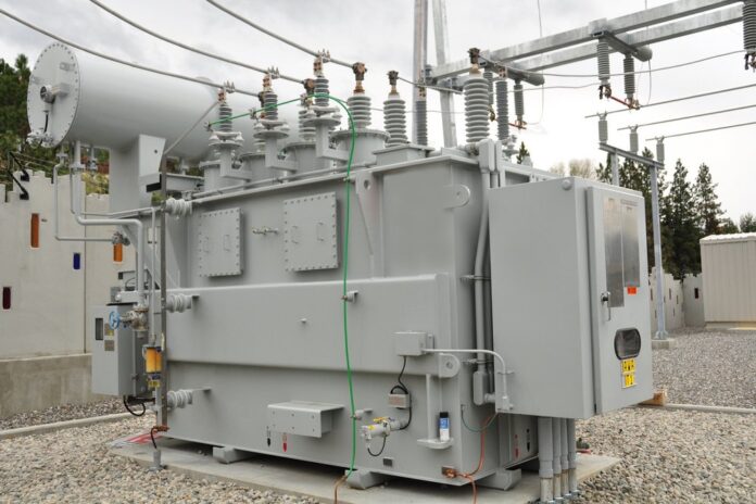
What is a transformer ?
A transformer is a device by which the amplitude of an alternating e.m.f. can be increased or decreased.
It does not affect the frequency of the alternating voltage.
It works on the principle of electromagnetic induction and makes use of two coils coupled together with a soft iron core.
Working Principle ;
A transformer cannot be used with direct current (D.C.) since its working is based on the principle that when there is change of magnetic field lines due to varying current in one coil, an induced varying current of same frequency flows in the other coil. If current in one coil is constant (i.e., d.c.), no induced current will flow in the other coil since there will then be no change in magnetic field lines linked with the coil.
There are two types of transformers :
(1) Step-up transformer, and
(2) Step-down transformer.
(1) Step-up transformer : The transformer used to change a low voltage alternating e.m.f. to a high voltage alternating e.m.f. (of same frequency) is called a step-up transformer.
(2) Step-down transformer : The transformer used to change a high voltage alternating e.m.f. to a low voltage alternating e.m.f. (of same frequency) is called a step-down transformer.
The different electric appliances that we use in our daily life require different working voltage e.g. a door bell needs 6 V while a TV requires several thousand volt. Therefore, both types of transformers are used so as to obtain the voltage requirement of the different appliances from our mains supply of 220 volt.
Construction :
A transformer consists of a laminated soft iron core made up from thin rectangular frames of soft iron placed one above the other and insulated from each other by a paint or varnish.
On one arm of the core, a coil P of insulated copper wire is wound. This coil is connected with the alternating source of e.m.f. (i.e., at the ends of this coil the input is given). This is called the primary coil. On the other arm of the core, another coil S of insulated copper wire is wound. The induced alternating e.m.f. is obtained across the terminals of this coil (i.e., output is obtained at the ends of this coil). This is called the secondary coil. The ratio of number of turns Ns in secondary coil to the number of turns No in primary coil (i.e., Ns/Np) is called the turns ratio.
The advantage of using a closed core is that it gives a closed path for the magnetic field lines and therefore almost all the magnetic field lines caused due to the primary coil, remain linked with the secondary coil (i.e., the flux linkage is nearly perfect).
Read More :
Difference between Step Up and Step Down Transformer


